Air and foam in oil
Excessive air in oil and excessive foam on the surface of the oil are two uninvited guests that maintenance technicians would prefer to avoid in their day-to-day work. This is because air bubbles in or on the surface of the oil can cause serious problems and therefore need to be kept in check. We show how the intake of air and the formation of foam are related and how lubricant analysis methods can be used to help to resolve this problem and prevent it from happening altogether. The OELCHECK laboratory is well equipped to respond to queries of this nature and has been officially listed as a provider of the Flender foam test following an audit by Dr Gajewski at Siemens Mechanical Drives.
Table of contents
Increased air content and its effects
All oil contains air. Depending on the type and viscosity, it may have an air content of up to 11% dissolved in its molecular structures. This baseline situation is not a problem. If the temperature or pressure is increased, air may be discharged from the oil, thereby reducing the oil‘s oxygen content – which otherwise facilitates oxidation – and potentially slowing the oil aging process. However, the air content may rise if, for example, the intensity of the bond changes due to impurities or by mixing together oil types with different properties. Fluctuations in pressure and temperature in particular can cause the air – whose volume is too high for it to be dissolved in its entirety – to become isolated in the oil as individual bubbles. Due to their low specific weight, these bubbles rise to the surface and burst. Usually, isolated air dissolves much more slowly in oil once it has become separated. This may also lead to the external intake of air. If the air absorption capacity in the oil is insufficient, it is often easy to detect air bubbles simply by looking at the oil. In addition to the oil frequently looking cloudy or milky, this can lead to serious issues (above all in high-pressure systems present in hydraulic units or turbines), including:
- Increasing compressibility of oil
- Declining output capacity of pumps
- Impaired lubricating effect through to a lack of lubrication
- Seal wear
- Declining cooling efficiency
- Increased oil oxidation
- Cavitation with selective material removal, often accompanied by noise
- The ‚diesel effect‘, where air pockets are compressed to the point that they ignite. Soot particles are created during this process and the oil becomes black.
Air release (LAV)
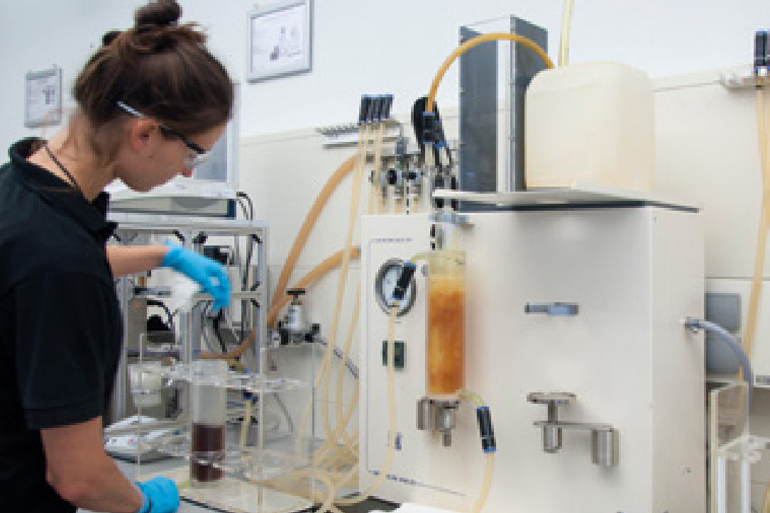
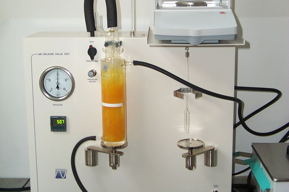
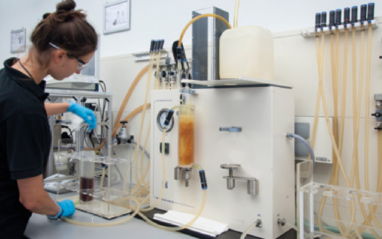
To minimise these negative effects or exclude them altogether, an oil needs to be able to separate surplus air as quickly as possible. This behaviour is determined in the laboratory and is referred to as its air release (LAV). The LAV value depends on the base oil type, additives, viscosity and temperature. Impurities and/or mixtures can also play a role in the size of the air bubbles. As an oil‘s air release time changes during its service life, it is recommended that OELCHECK performs a special test on samples taken from hydraulic and turbine units. The LAV of a used oil in comparison to that of a fresh oil or a previously analysed trend sample can reinforce assertions as to the cause of an operating fault or damage, and offers an indication as to its continued usage. Conclusions as to why the LAV value has deteriorated can usually be drawn after looking at other values gained from an analysis. To determine the LAV in a standardised manner in accordance with DIN ISO 9120 and ASTM D3427, the time (in minutes) is measured in which it takes for the air, which is discharged into and initially dispersed in the oil, to be separated again up to a residual content level of 0.2 Vol. %. Preheated air is then discharged via a nozzle at a fixed pressure over a specific period of time into a 200 ml sample of the oil to be analysed. The dispersed air bubbles then escape from the oil over time with the aid of the oil‘s density. This process is recorded graphically until the volume no longer changes. The time it takes from when the air intake is switched off until the point at which the density no longer changes is the air release time.
Good output values guarantee that the oil can be used for a relatively long time. This is why the LAV of brand-new hydraulic or turbine oils should not exceed the limit values specified here:
| Air separation characteristics for fresh oils Limit values of traditional requirement standards | ||||||
| ISO VG/Typ | 32 | 46 | 68 | 100 | (150) | (>320) |
|---|---|---|---|---|---|---|
| Turbine oil DIN 51515, ISO 8068 | 5 | 5 | 6 | x | x | x |
| HLP/HM hydraulic fluid DIN 51524/2, ISO 11158 | 5 | 10 | 13 | 21 | 32 | x |

Increased LAV – corrective measures
volume of additives or the viscosity indicate that the oil has been mixed with another type or if the IR spectrum suggests that the oil has oxidised, nothing can be done except to change the oil. Adding another element to the mix, e.g. anti-foam additives, is generally counterproductive.
Why oil foams
When determining the air separation characteristics, air bubbles rise to the oil‘s surface and dissolve into the air. Only the „saturated air“ remains in the oil. The moment of truth comes if the air bubbles that have risen to the surface do not burst straight away. If this process continues for a long period of time, the bubbles form a layer of foam on the surface of the oil. This foaming tendency can therefore have an extremely negative effect on the oil, despite the LAV – measured via the density in the oil phase – not yet showing any striking results. Whether foam forms on the oil depends on its surface tension, viscosity, operating temperature and air intake method. Impurities, oil mixtures and oil oxidation all exacerbate the oil‘s foaming tendency.
Foam and its effects
Refilling the oil is not a problem if the air bubbles that rise to the surface of the oil burst quickly. However, this is not the case if the following effects are observed:
Stable blanket of foam on the surface of the oil
This may impair the cooling effect and lead to a rise in operating temperature. The oil then becomes more oxidised and wears out more quickly. The operating viscosity can also be reduced in places.
Oil/air emulsion throughout the oil reservoir
Along with the negative effects that arise due to the presence of a blanket of foam, the sensors that monitor the oil level are impaired. In this case, pumps may start to draw in a mixture of oil and air instead of pure oil. In a hydraulic system, this can lead to cavitation and the ‚diesel effect‘. Foam in bearings prevents a hydrodynamic lubricating film from being created. Foam in the gear unit often leads to significantly higher operating temperatures due to diminished friction performance. Furthermore, the oil ages at a faster rate and the operating viscosity is reduced.
An overflow of foaming oil
Leaks caused by oil overflowing from a unit or gearbox – along with loss of oil and environmental contamination – simply do not bear thinking about. That said, they unfortunately occur time and again. In addition to the aforementioned risks, a loss of oil from excessive foam can result in insufficient oil in the system and therefore a lack of lubrication.
Foaming tendency
Oils used in gear units, turbines or hydraulic systems are subject to a special testing rig in the laboratory in order to determine its foaming behaviour in practice in accordance with ASTM D 892 and ISO DIS 6247. The test looks at how long it takes before the foam disintegrates. Preheated air is discharged via a spherical, porous stone into a 410 ml sample of oil to be tested. This leads to an air in oil dispersion in the form of fine bubbles. These bubbles rise to the surface and create a layer of foam. The foam volume is measured immediately after the air is switched off and again after 10 minutes have elapsed. There are no generally valid limit values for an oil‘s foaming tendency. However, the development of the trend and the change in comparison to fresh oil do constitute criteria for assessment. The VGB guidelines for turbine oils with a limit value of 600/0 ml/ml can be used for orientation purposes. However, each case must be assessed individually.
The practical Flender foam test
The Flender foam test was developed due to the fact that determining the foaming tendency via „foam bricks“ has only limited applicability in practice. The practical test is primarily used for assessing gear oils, particularly when a combination of oil types or impurities have resulted in excessive oil foaming in the gears. In addition, leading gear manufacturers require gear oils to have passed a Flender foam test before approving it for use in their gearboxes. The testing method was originally used by A. Friedr. Flender AG as an in-house test for assessing the foaming tendency of industrial gear oils. The company merged with Siemens AG in 2010 and commenced operations under the name Siemens Mechanical Drives. Today, it is the Group‘s specialist for gears and couplings. The „Flender“ brand name has been retained. The extensive product portfolio ranges from individual components to complete drive systems for virtually all industrial applications.
Today, the Flender foam test is standardized according to ISO 12152. Furthermore, Siemens Mechanical Drives now lists the laboratories approved for the Flender foam test following an audit commissioned by Siemens. For the audit, the independent laboratories must have the requisite test benches and trained staff, must be certified or accredited, and must publish the test results in a standardised report. OELCHECK is currently one of very few laboratories officially appointed by Siemens Mechanical Drives to perform the test. In the Flender foam test, a gearbox housing is filled with 1,000 ml of oil. A gear pair with equal-sized gear wheels is used to stir the oil for five minutes at an RPM of 1405 min-1 at 25°C. The gear pair sits horizontally to the halfway point – the centre of the gear wheel – in the oil sump. The high RPM and the half-submerged gear wheels enable the oil to be stirred at a high speed, which draws in air. This leads to the formation of foam in all types of oil, and the oil volume increases as a result. The oil level can be read before, during and after the test via a graduated scale on a glass pane in the wall of the gearbox, and the change in the oil‘s volume can be stated directly as a percentage. An oil‘s foaming tendency can be assessed based on the percentage increase in volume displayed by the test oil one minute after the test rig is stopped. The oil/air dispersion volume (%) can be calculated five minutes after stopping the rig. OELCHECK directs a camera at the glass pane to record the test run and stores the data accordingly. The test results are classified as follows according to the specifications of Siemens Mechanical Drives: Rise in oil volume one minute after stopping (%)
- < 5 % good
- < 10 % satisfactory
- < 15 % acceptable
- > 15 % not acceptable
However, these values are only valid for the text gearbox and the standardised method. They are based on the experience of Siemens Mechanical Drives gained through meeting the requirements for oils in Flender gear units. The 15% stated above is not an actual limit for foam formation in gear units. Volume rise in oil/air dispersion five minutes after stopping (%)
In general, an increase of up to 10% is tolerated. This limit value of 10% free air is set by leading pump manufacturers to avoid cavitation. The five-minute time window is the result of design guidelines issued by Siemens Mechanical Drives, and relates to the minimum ratio of oil volume and pump capacity.
How to avoid foam
Supplementary air, impurities, mixtures and anti-foam additives – these four factors have a major effect on exacerbating an oil‘s foaming tendency. The formation of foam can be avoided by observing a few basic rules.
Supplementary air
The oil pump may draw in so much fresh air with the oil that it can no longer be separated. Causes may include:
- Worn seals
- Leaks in the hydraulic pump or pipes
- Fill level in the tank is too low or too high
- Change in flow conditions in the tank or the pump‘s intake manifold.
Contaminants
The type and quantity of impurities govern the resulting effects. If the oil contains water and/or dirt particles, the air bubbles are retained in the oil in a dispersed manner. If the oil is old, reaction products from the oil oxidation process can, for example, change the surface tension so that the air bubbles that have risen to the surface no longer burst. In other words, oil maintenance and oil aging have a major effect on the oil‘s foaming tendency.
Mixtures
Foam rarely forms in systems with non-alloyed or mild-alloyed oil charges. However, the more additives an oil contains, the greater its tendency to foam. To counteract this effect, oils are charged during the production process with anti-foam additives that are usually based on silicone. Caution when working with oil mixtures containing different additives. Even if oils are approved for the same application or meet the same specifications, this does not mean that they are compatible with one another. Foam can still form if an oil with a low concentration of additives is mixed with a product containing a high concentration of additives. Mixing synthetic oil with mineral oil can change the surface tension. An oil analysis can be performed to quickly find the cause. A complete oil change is usually required after this. To avoid having to perform these highcost measures, take care not to mix the oil types. Proper lubricant management is the best form of insurance against this.
Anti-foam additives
Foam inhibitors are polar active agent combinations with a component that is soluble in oil. Silicon-based materials are common. However, not every foam inhibitor contains silicon. Anti-foam additives are systematically added to lubricants during production. They inhibit the cohesive force of the oil molecules and reduce surface tension. This makes the oil film covering the air bubbles thinner, meaning that they burst more easily, which reduces the chance of foam formation. If an excessive amount of foam develops during operation, the anti-foam additives may have been filtered out. They should not subsequently be added by the end user, as an overdose can be counterproductive. The polar active substances in the foam inhibitor provide the basis for the air and oxygen to bind, with the result that the oil ages more quickly. The lower surface tension reduces the size of the air pockets in the oil (i.e. below the surface of the oil). The oil‘s air release is then impaired. In general, always be careful when retroactively adding anti-foam agents.
Only a lubricant analysis is able to effectively determine the condition of the oil and its additives. An OELCHECK diagnosis of the values recorded during the analysis provides a strong basis for deciding which measures to take.
Weitere Informationen
OELCHECKER Summer 2017, pages 5-7


![[Translate to "English"] Flender-Schaumtest [Translate to "English"] Flender-Schaumtest](/fileadmin/user_upload/img/wiki-pics/FlenderSchaumtest_01.png)
![[Translate to "English"] Prozentualer Volumen-Anstieg der Öl-Luft-Dispersion [Translate to "English"] Prozentualer Volumen-Anstieg der Öl-Luft-Dispersion eine Minute und fünf Minuten nach dem Stopp](/fileadmin/user_upload/img/wiki-pics/luft_und_schaum_im_oel.png)


