O.P.A. - Optical Particle Analysis
Year of publication: 2002
A high degree of oil purity extends the service life of the parts that come into contact with the oil and causes the oil itself to age less quickly. Both in lubricated systems such as rolling and plain bearings or gears, where no hard wear or contaminant particles should disturb the thin lubricating film, and in hydraulic systems, knowledge of the cause and nature of a contaminant plays a major role. Particle analysis, either by AES and particle counting for hydraulic oils or by AES and O.P. A. for gear oils, is therefore an essential part of oil testing for a meaningful diagnosis.
Table of contents
OELCHECK gets to the bottom of impurities in oil with a powerful particle counter. The counted values serve as a basis for determining the respective purity class of the examined oil and show in the trend development whether the oil is cleaned well enough.
The classic particle counting method commonly used today uses a laser sensor to determine the number and size of particles per 100ml of oil. The sensor records the particles in the oil that block the laser light as shadows in the form of electronic peaks. However, the count does not distinguish whether the particles are soft or hard, nor does it provide any information about their shape.
This means that no further conclusions can be drawn about the origin and impact of the particles in question. In order to obtain more precise findings, further investigations must be carried out such as
- the atomic emission spectroscopy
- the double check the determination of "solid contaminants"
Manner of operation
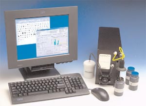
Optical particle analysis goes far beyond classical particle counting. OELCHECK was the first user in Europe to install an LNF (LaserNet Fines) device in its laboratory for this purpose, which was developed by Lockheed-Martin for checking gear oils in helicopter gears.
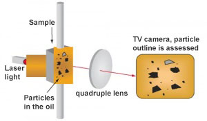
The inspection method combines extremely bright laser light, which makes all particles in the oil visible, with the "artificial" intelligence of an observer that evaluates these particles by geometric shape.
A few ml of the homogenized and tempered oil sample is pumped at a continuous rate through a viewing window (similar to a 2-pane insulating glass). Laser light generated by a diode with a frequency of 350m/sec shines through this window. In the rectangular window, the oil film is spread over a very thin area and is thus in almost all cases – at least for the laser light – so transparent that all contours of the contaminants in the oil are sharply outlined. In addition, behind the window there is a 4-fold lens with the help of which the non-oil components are magnified in such a way that they can be captured by a permanently installed electronic CCD camera in the form of a black-and-white photo.
The particles that reflect the light appear as dark areas on the image. Within one second, 30 such particle photographs are taken. Similar to a hand-held camera, the electronic camera stores the images and forwards them to a computer. Specially developed software is used to catalog the outlines of the parts and assign them to specific categories such as fatigue wear, chip-like wear, non-metallic contaminants, air bubbles, water droplets, fibers, and so on. As under a microscope, the photographed parts can be further enlarged (zoomed), measured and viewed. The number of particles per category and their size enables a conclusion to be drawn about the cause of the depicted wear or contamination in the oil.
Performance
Inexpensive test methods do not provide all the information about the causes of wear. For example, determination of metals with AES is limited to particles smaller than 5μ. The PQ index shows only magnetizable iron particles.
Particle counting does not distinguish between soft or hard particles. With the O.P. A., the individual particles in the oil stream are imaged by photography. With the help of the computer, the particles can be enlarged and measured. Using the outline, size and appearance, the individual particles can be cataloged into different types of wear and aged oil components.
Particularly in the case of slow-running planetary gears (oil circulation systems, large engines, complex hydraulic systems, oil-lubricated systems), which are difficult to monitor with vibration or other sensors, the O.P. A. provides essential information about the wear condition and its cause.
The typical images of an optical particle analysis are sent together with the well-known laboratory report as a 3-page printout. The result is commented on separately in detail.
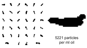
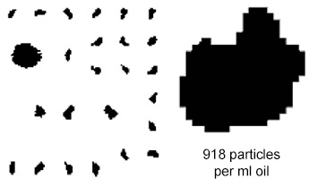
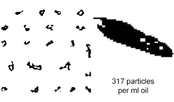
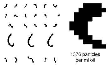
The following images are taken from an examined industrial gear oil CLP 320, as used in gears of wind turbines, in screw presses in the sugar industry or in extruders in plastics production. The oil, which has been in use for about 11,000 h, shows a significant increase in wear particles in the conventional analysis and a simultaneous degradation of the oil additives. An oil change and gear inspection for micropitting and fatigue wear was recommended. Details of the analysis are clear from the figures and the number of particles per type of wear using optical particle analysis.
By far the majority of wear particles can be assigned to this group.
Sliding wear is caused by local contact between the roughness peaks. The cause of this metallic contact is too high oil temperatures, too low an operating viscosity or too high a specific load on the tooth flanks due to overloading or vibration.
Fatigue wear
Under load, oil additives react and form long-chain chemical compounds, which are imaged as so-called "tribopolymers" as elongated, partially translucent particles. These mostly soft particles, formed by chemical reactions of the oil additives, do not interfere in the slow-running gear, but often still promote the formation of an optimum lubricating film. In comparison with the wear particles, this proportion is unexpectedly low.
Cutting wear
Chip-like particles are clearly visible. They are a clear indication of a machining wear process. Since the dust content detected is low when the iron content in the sample is high, this form of wear can only have been caused here by hard metallic iron particles.
On the basis of the O.P.A., OELCHECK was able to recommend the use of a higher viscosity oil with more suitable additives. In this way, the gear will be better protected in terms of sliding wear.
| O.P.A. particle analysis with particle photography | automatic particle counting with laser sensor | optical particle counting by microscope |
|---|---|---|
|
|
|
|
|
|

